TODAY August 5 2025 A SECOND PART HAS BEEN ADDED TO THIS SITE, NOT PRESENT INITIALLY
A COMPLETELY NEW AND DIFFERENT WAY OF IMAGINING COMPRESSION AND ABSORPTION HEAT PUMPS AND THE HEAT EXCHANGERS DEDICATED TO THEM, AS WELL AS A NEW WAY OF SEEING THE TECHNOLOGY OF THERMAL SOLAR AND GEOTHERMAL SYSTEMS.
PRELIMINARY CONSIDERATIONS
Efficiency is considered as the ratio between the amount of thermal energy that the machine makes available and the energy it uses to operate (usually electrical energy) Coefficient Of Performance =COP.
To face reality, however, it would be necessary to understand whether it is still valid or not, the values obtained today from the formula, theoretical max COP = Te / (Tc - Te) , where Te is the condensing temperature and Tc is the condensation temperature in Kelwin degrees.
Granted that this formula is reliable even under different working conditions, such as a different condensation process or a different evaporation process, different heat exchangers, and an efficient heat storage system, the fact that these different factors require higher evaporation temperatures and lower condensation temperatures, raising the value Te in the numerator and lowering the value (Tc - Te) in the denominator, undoubtedly increases the COP value.
Although this fact is easily understandable, I do not understand why the first draft of my work described in the first part of the site has been ignored by every entity consulted, whether private or public, and although I have entrusted my entire future to this work, I have decided to raise the stakes by publishing, in open display, all the rest of the work completed over years of reflection.
Let's make some examples about the current efficiency values of heat pump systems for air conditioning that are currently on sale, to ask ourselves why there is this stubbornness to continue producing old systems that could truly be improved a lot and find their new market space.
- For very cheap air conditioning appliances consisting of two units, one external and one internal (split), for thermal powers of 8,000 - 12,000 btu with an average cost of 350 to 600 euros/dollars, the average efficiency value is COP = 3.
-For higher-end air conditioning appliances, consisting of two units, for heat outputs of 8,000 - 12,000 btu, the average efficiency value is COP = 4.
-For air-to-air or air-to-water heat pumps with a low condensing temperature of about 55- 65°C, with a sufficient thermal power for medium-sized homes, with an average cost of 6,000 euros/dollars, the average heating efficiency value is COP = 5.
- Monobloc air conditioners (with a single unit and therefore without an outdoor unit) with a thermal power of 12,000 btu, with an average purchase price of 600 to 1,400 euros/dollars have an average heating efficiency value of COP = 3.7 . As you can see, monoblock air conditioning units are usually less efficient than dual units split systems, but there is no technical obstacle to creating monoblock units with a level of efficiency that is double that of the current ones. There are already some examples included in the Sofia system illustrated in the first part of the website, but of the many illustrated in the second part, it will be necessary to verify their efficiency by testing them through prototypes, because they are really out of the ordinary.
-For air-to-water hydronic heat pumps with high condensing temperature to power radiator or fan coil systems, the average heating efficiency value is just COP = 1.7. This low efficiency value is due to the fact that inducing a higher condensing temperature than the usual 55-65°C, in a heat pump system, for the operating needs of radiators, inevitably causes the system to lose efficiency.
- An absorption heat pump system with an aqueous solution of ammonia has an average efficiency ratio, and therefore a COP = 1.4 but in this case, it must be taken into account that a large part of the operating energy is not electrical but thermal and is therefore an efficiency value of about 47% higher than that of a simple condensing boiler that can recover 95% of the superior heat power of the fuel.
It is therefore clear that the efficiency of today's heat pumps can still be greatly improved. In the prior study of pre-existing patents, I have seen proposals for different refrigerant circuits, some with two compressors, with two or more expansion valves, or with an open circuit superimposed on the closed refrigerant circuit, but all for a modest gain in efficiency. The best solution I have seen among the existing patents, inserts a puffer with two heat exchangers, one that connects the condenser to the expansion valve and the other that connects the evaporator to the compressor suction thus increasing the temperature of the refrigerant liquid to be evaporated before it enters the evaporator and cooling the refrigerant vapor to be condensed before it enters the condenser. But even these solutions only slightly increases efficiency. It is therefore perhaps better, to intervene in a traditional loop circuit, improving a) the condensation ssoreprocess, changing it for a faster and more efficient one b) With a different condensation process and more efficient heat exchangers, it is possible to raise the temperature and lower the pressure at the condenser, reducing the pressure difference with the evaporator. c) the evaporation process, changing it for a faster and more efficient one. d) With a different evaporation process and more efficient heat exchangers, it is possible to lower the temperature and raise the pressure at the evaporator, reducing the pressure difference with the condenser. e) In some specific cases, it is possible to use a special compressor described here that dispenses with the use of the expansion valve recovering part of the energy used for the compression of gas or refrigerant vapor. The development of each of these points can increase the efficiency of the system, imagine a heat pump system that includes various of these features together. Already in the first part of the site, a system is presented that I have called Sofia, which combines new heat exchangers with a new condensation process and many new and groundbreaking solutions will be shown to you in the second part of this site.
If a heat pump system is asked to increase its thermal power beyond its usual maximum, the only way is to lower the evaporation temperature, raise the condensation temperature, or do both, still losing efficiency, because this corresponds to a lower pressure in the evaporator, a higher pressure in the condenser, and therefore a greater pressure difference between the two environments, which increases the effort and thus the work required from the compressor and therefore the amount of energy it absorbs to operate.
However, if faster evaporation or condensation processes are employed, a greater amount of refrigerant will change state without needing to modify the evaporation and condensation temperatures and pressures, thereby saving energy. The same occurs if heat exchangers with lower intrinsic thermal resistance are used, provided that there are sufficiently fast evaporation and condensation processes downstream. This reasoning suggests that, from new heat exchangers and more efficient condensation and evaporation processes, we should expect a positive outcome in terms of increased system efficiency. If, however, a more efficient heat pump system is desired, sensors and an electronic control system are needed so that when switching to supplying lower thermal powers, it does not operate intermittently but can lower the pressure at the condenser and raise it at the evaporator in order to reduce the pressure difference between them, thus reducing the consumption of the compressor. Reduced load performance. On a technical site I found the statement: In case of operation at a thermal power reduced to 70%, that is, a capacity ratio CR < 0.7, the heat pump loses any performance advantages. This means that the current systems by reducing the thermal power do not actually reduce the pressure difference between evaporator and condenser. Perhaps with the use of the current fin-tube (finned pack) heat exchangers, this mode is currently not made possible? Another reason to change, wouldn’t you agree?

HOW THE DIAGRAM WORKS
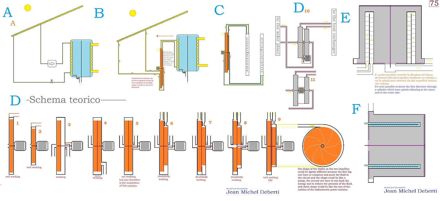
Since the world of heat pump design refuses to abandon traditional heat exchangers with finned heat exchange surfaces like finned pack heat exchangers, microchannel heat exchangers or finned tube heat exchangers, I thought about this integration to my patent applications to allow the use of the new condensation process also with the use of these old types of heat exchangers. The figure illustrates how the condensation of the refrigerant vapour takes place in a tank, while one or more heat exchangers simply cool the internal liquid mass heated by the condensation of the vapour. The new heat exchangers described in the patents filed, to use this new condensation process, do not need this tank, and the condensation takes place inside the exchanger used as a condenser. So, let's explain how it works. In the current condensation process, the environment in which condensation takes place, is the internal environment of the heat exchanger, which is mainly occupied by the refrigerant vapour to be condensed, which condenses on the colder internal surfaces of the heat exchanger by pouring downwards from where, liquid comes out of the exchanger through the duct which, after the expansion valve, carries it to the evaporator. In the new condensation process, on the other hand, the internal volume of the condensing room is full, not with steam but with liquid refrigerant, in a similar way to how it is already in the evaporator. As already mentioned, only with regard to the specific case illustrated, the condensing environment is not that of a heat exchanger but that of a tank, because this allows the new condensation process to be applied with the use of conventional heat exchangers, while with the use of the heat exchangers described in the patent applications, the condensation of the refrigerant vapor takes place inside the heat exchanger. The inlet and outlet points of the refrigerant on the tank are connected by a short recirculation duct equipped with a small circulation pump. There may be a liquid-steam separator at the outlet of the tank because, if a higher heat power is required from the appliance or system, a greater quantity of steam can be pushed into the condensing tank and part of this steam may not be able to condense and in order not to accumulate, it will be necessary to remove it, connecting it to the compressor intake by means of a duct
equipped with a shut-off valve and a reduction device so that this way is only open when needed and does not cause too much pressure to be lost in the condenser. The condensation of the steam in the tank releases heat into the liquid mass which, in the case of heat exchange with air, can also be removed by conventional finned pack heat exchangers, as shown in the figure, or in the case of heat exchange with water, can be removed by plate heat exchangers and the extracted heat can, for example, heat hydronic systems with radiant surfaces. Let's examine the reasons for the increased efficiency of this condensing system. First of all, it allows a better penetration of heat through the heat exchange surfaces because the traditional system provides that the condensing environment is full of steam and a gas or steam that is immobile or moving very slowly in the heat exchanger, is a very poor conductor of heat while, in the new system, on the other hand, the condensation environment, It is filled with fast-flowing liquid due to the recirculation circuit. In the traditional system, the steam can only condense close to the surfaces of the exchanger. In the new system, on the other hand, the continuous recirculation of the liquid through the condensation environment, causes the liquid to cool and the vapor to be condensed coming from the evaporator, is blown and dispersed in a myriad of small bubbles in this cool liquid mass recirculating stream that enters the condensation environment and the vapor bubbles implode, condensing at every point of the internal volume of the condensation environment, which, let's remember, in this case is a tank. Since, in this case, condensation takes place in the tank, the heat exchangers connected to the tank only serve to cool the internal liquid mass and for this reason they can be common finned pack exchangers, or plate exchangers, if the cooling takes place with water instead of air. The figures, including those at the bottom of the drawing, illustrate how to prevent cooling vapour bubbles from entering the heat exchangers, or show how to effectively disperse the vapour into the liquid mass of the tank. Since the new process can condense steam faster, it can do what would happen with the traditional process if the heat exchanger had a higher overall thermal conductivity. Therefore, if the new condensation process involves a virtual decrease in the thermal resistance of the exchanger, or a virtual increase in its general thermal conductivity, then, if the system is not required to have more thermal power, it can afford to lower the condensing pressure, which will decrease the pressure difference between evaporator and condenser and the less effort required from the compressor will increase the efficiency of the system. In the event that the appliance or system includes the reversal of the functions from winter heating to summer cooling and vice versa, with an exchange of evaporator and condenser functions between the heat exchangers of the system, the system scheme must become symmetrical and the presence of a recirculation circuit makes the scheme a little different from the simple loop scheme (ring circuit consisting of the succession of condenser > compressor > expansion valve > evaporator > ) of current appliances and systems. It is all explained in the technical reports which I already sent by post to most of you perhaps three or four months ago. For a matter of symmetry, it is possible to repeat the same tank-heat exchanger scheme also at the evaporation side of the system and in that case, it will be sufficient to turn off the pump of the recirculation circuit and evaporation will take place both in the heat exchangers and in the tank. It is possible to make the evaporation take place exclusively in the tank if a lamination valve or in any case pressure reduction valve is placed, before the refrigerant exing from the exchangers, enters the tank because the fluid will thus be slightly overpressured in the exchangers due to the pressure of the circulation pump and the action of the aforementioned valve. With the same intent, the refrigerant could also be diluted with a different, heavier liquid, not intended for evaporation, which at the bottom of the tank would pass through the heat exchangers absorbing heat and then, falling like rain inside the tank, could pass this heat to the refrigerant which, heating up, would evaporate. The use of a dilution liquid allows the use of larger heat exchangers with a larger heat exchange surface. However, a real advantage caused by these choices, must be verified experimentally. To the scheme described here, however, I prefer the application of the new condensing process to the cylindrical helix heat exchangers described in my patent application that I will send you this time to an e-mail if you want to indicate me a contact address, preferably from one of your heat pump expert engineers who can evaluate it for you.
FIRST PART OF THE SITE, PUBLICHED ON DATE 5 august 2025 regarding the patent applications filed on in Italy and Switzerland on December 19, 2023. All patent applications referenced in the first part of this site, are for invention patents and not for utility patents.The figure on the front page serves to provide an immediate idea of the projects contained on the site and concerns an adaptation of the new condensation process to the use of today's most widespread air-water or air-refrigerant fluid heat exchangers, those with finned coils called finned pack heat exchangers.Only in the specific case of this adaptation, the condensation process does not occur inside a heat exchanger, but within a tank. Although in the initial version described in the patent application, the condensation takes place in a heat exchanger patented by me, dispersing the steam to be condensed in the liquid flow that circulates through a circuit equipped with a small pump connecting the outlet and the inlet of the exchanger, in this version the condensation still occurs by dispersing the condensing steam into the flow of refrigerant liquid that recirculates between the outlet and inlet of the tank, this time similarly, through a circuit equipped with a small pump connecting the outlet and the inlet of the tank. The first part of the site contains the technical descriptions of the patent applications filed, the list of which is provided below.
1Condensation process and absorption process of refrigerant vapour and related compression and absorption heat pump systems.
Original title in italian:
Processo di condensazione e processo di assorbimento di vapore frigorigeno e relativi sistemi a pompa di calore a compressione e ad assorbimento.
Originally filled on 19 Decenber 2023 in Italy and Switzerland with the codes: UIBM 102023000027114, and CH 001418/2023 .
After the request of the European Patent Office to split this patent application, on 11 October 2024 the UIBM 102024000022671 and the UIBM 10202400002692 were re-submitted, only for Italy, which differ from the original filed on 19 December 2023 only for claims and a third application was also re-filed, the UIBM 102024000022638 which, compared to the original, has the additional description of the application of the condensation process in the tank with cooling by means of common finned pack heat exchangers. These three patents will take the place of the original UIBM 102023000027114 approximately starting from September 19, 2025.
2Heat exchange systems using a helical heat exchanger.
Original title in italian:
Sistemi di scambio termico che utilizzano uno scambiatore di calore ad elica cilindrica.
Italian patent application no. 102023000027138 and Swiss Patent Application No. CH001419/2023 both filed on 19/12/2023 and remained unchanged.
3Heat exchanger with centrifugal fan function
Original title in italian:
Scambiatore di calore con funzione di ventilatore centrifugo.
Italian patent application no. 102023000027129 and Swiss Patent Application No. CH001420/2023 both filed on 19/12/2023 and remained unchanged.
4"SOFIA" system for compression or absorption heat pump.
Original title in italian:
Sistema a pompa di calore a compressione o ad assorbimento.
Italian patent application no. 102023000027162 and Swiss Patent Application No. CH001421/2023 both filed on 19/12/2023 and remained unchanged.
The new refrigerant vapour condensation process described in text and figure at the beginning of this website, and which deals how to apply it using common finned pack heat exchangers, was developed after the first filing of the patent application of 19 December 2023 and being missing there, it should be considered an additional part of the technical report of the new condensation and absorption process of refrigerant steam downloadable at this link.
SECOND PART OF THIS SITE
Shortly after filing the patent applications described in the first part of the site, I wrote repeatedly, more than a hundred letters (e-mail contacts with executives and engineers are confidential and rarely available) to the headquarters of all major global manufacturing companies asking them to seek feedback from their research and development center, but most of them replied that they did not accept pending patents, only already approved ones. I then wrote to the companies with a request to collaborate, patenting in their name the things contained in this second part and making myself available on-site to participate in the development of study prototypes. In just a couple of cases, I initially received a significant expression of interest, followed by the news that, however, their engineering board did not want to have me among them. In fact, why should engineers who already have so much work to do, also have to follow the instructions of someone who is not even a graduate and he doesn't even know how to speak English well? Having worked for 16 years drafting these ideas and almost two more to draft what were supposed to be the first patent claims, confident that I would find some form of agreement, I used almost all of my financial resources. Therefore, I decided to publish in open access in this second part, also the remaining part of my work in the hope that this time it cannot be ignored and some large company would prefer that I be present during the realization and testing of prototypes to confirm adherence to the projects, avoiding misunderstandings. Lastly, I want to clarify that my initial idea of an agreement with the manufacturing companies was to open a company that would bring all the representatives of the associates together around a board table and work to promote the dissemination of new techniques by providing the necessary information to potential customers, repair technicians, installation technicians, and design engineers, finance courses and training schools, and for the authority that holds the patents, oversee quality control and conformity of the products on the market, initially being able to propose compatibility of spare parts between different brands.
NOTICE The free exposure of the objects in this second part renders them "known items" and therefore not overly patentable; however, having waived the right to patent them, I have not conducted any prior art search regarding any existing patents. Interested parties in their production and commercialization are therefore required to verify this by conducting, at their own expense, preliminary prior art searches to ensure absolute certainty of the non-existence of any previous patent constraints. If, instead, one intends to help spread the ideas described here, it must be specified that no examination of patent precedence has been conducted for them. This site requires payment and will lose all the data it contains upon expiration. It may therefore happen that someone makes complete copies and continues to disseminate it freely on other platforms.
Jean Michel A. J. Deberti
FOR ALL THE THINGS DESCRIBED IN THE SECOND PART OF THIS SITE, NO PATENT HAS BEEN REQUESTED NOR HAS THERE BEEN ANY PATENT PRIORITY EXAMINATION, WHICH THEREFORE IS THE RESPONSIBILITY OF THE INTERESTED PARTIES. THIS IS NECESSARILY A QUICK EXPOSITION. TO PROVIDE MORE DETAILS AND FOLLOW THE REALIZATION AND EXPERIMENTATION OF PROTOTYPES, I AM AVAILABLE FROM ONLINE WORK TO A JOB WITH RELOCATION.
It is well known that the Thermal exhange between two fluids separated by a surface, increases if both fluids are in the state of flowing motion, rather than quiet and the most effective way to realze this condition, is to drag the fluid along a heat exchange surface, of circular cross section, by means of a rotating centrifugal impeller. I would like to call heat xchangers based on this principle, dynamic rotary (or rotating) heat exchangers, abreviating in dr heat exchangers. We will see many ways of making them, stating with the air to air heat exchanger described in the first part of this site.
In doing so, they sacrifice a small amount of electrical or mechanical energy to increase heat exchange or allow it to take place even with smaller temperature differences and this caratteristic rises the efficiency of any heat pump systems including refrigeration and air conditioners and even absorption heat pump systems. I do not know if the definition of dynamic rotary heat exchangers is available, by which I mean heat exchangers equipped with a centrifugal impeller which pushes the fluids to flow qickly on heat exchage surfaces. A feature of these heat exchangers, is that the rotating impeller generates a head in the same way as fans or centrifugal pumps, and the combination of the linear motion of the fluid passing through the heat exchanger with the rotational motion around the heat exchange surfaces of circular cross-section (cylindrical or conical ones) , results in a spiral-shaped motion.
table 1 : Having defined the general characteristics of a whole family of heat exchangers called 'dynamic', I begin by describing the first series, the dynamic cylindrical, conical or discoidal cavity heat exchangers with internal spiral.
The heat exchange element of the heat exchangers of this table, is a cylindrical cavity consisting of a spiral surrounding a central cylinder, the whole enclosed in a second cylinder so that the spiral is in the space between the two concentric cylinders. A liquid or gaseous fluid flows in the space between the two cylinders following the path between the coils of this spiral. In the heat exchangers illustrated in this table, the fluid that generally flows through the impeller is air alone or together with water, and both the fluid flowing through the impeller and the fluid flowing inside the cylindrical gap take spiral-shaped paths on both the inner and outer sides of the heat exchange surfaces. The speed ad the time at which the fluids remains in flowing over the heat exchange surfaces, is the strength of these heat exchangers. Heat exchange with water takes place in the presence of air and the water, introduced into the upper part of the exchanger, is dragged with it onto the cylindrical heat exchange surface by the fast flow of air generated by the rotation of the impeller. As in the case of centrifugal fans and pumps, the air outlet environment of the casing of the heat exchanger can be circular or snail-shaped. The figures at the bottom of Table 1 show compression heat pump systems realised with this type of heat exchanger. Some of these figures were made before my discovery of the condensation process which is explained in the first part of this site and which would be the most suitable because it allows, by filling, every point of the heat exchange surface to be covered with liquid refrigerant and to use a very simple form of internal spiral of the heat exchange element. In figure R of this table 1, in fact, to apply the classic condensation process there is the use of a complex shape of the spiral profile and such that the vapour can be separated from the refrigerant liquid. Note, however, that in figure U of the table, the positions of the refrigerant and the water are reversed, because it is the water that flows in the cylindrcal cavity while the refrigerant, in this case, is introduced into the space occupied by the impeller. The rotation of the impeller pushes the rotation of the refrigerant vapour against the inner cylindrical surface of the heat exchange element, and this is for both, the condensation and evaporation process. The classic condensation process is thus enhanced, while this figure, for the first time, also introduces a new, more efficient mode of the evaporation process. In this new mode, evaporation takes place from a thin layer of liquid refrigerant in which the refrigerant to be evaporated is not subjected to hydrostatic pressure, the viscosity of the liquid braking the rise of the vapour bubbles, and above all, in a dry vapour environment, allows the evaporation of the refrigerant at temperatures lower than boiling temperature, greatly increasing the efficiency of compression heat pump systems and later, we will see other examples of this with dynamic heat exchangers of a different type. Table 1 also deals with various possible forms of the part concerning the exit of the gaseous fluid from the exchanger, also with regard to questions of kinetic efficiency, since these heat exchangers are in part also a centrifugal fans. Careful attention to kinetic efficiency is important because in a heat pump system based on this type of heat exchanger, electricity is not only absorbed by the compressor, but also by the impeller motor of the heat exchangers, and a high kinetic efficiency reduces consumption. The figures L5 and P1 consider the possibility of lapping the outer cylindrical surface of the cylindrical heat exchanger element with air, and the possibility of using multiple cylindrical heat exchanger elements arranged concentricly.
Table 1B : Extension of the previous table, there is proposed the extension of the heat exchange surface by introducing, in addition to the cylindrical heat exchange elements, others heat exchange elements with a discoidal shape in which, the element that determines the path taken by the internal fluid, is a flat spiral constitute by a foil or by a tube or is in the shape of a circular labyrinth, as shown in figures 8 and 9. Three different but equivalent versions of the cylindrical heat exchange cavity are possible. Of the first we see two slightly different examples in figures V and W of this table. The dynamic exchanger with impeller realised with the heat exchanger element in figure V, is realised by means of a rectangular profile passed perhaps hot through the calender to be curved into a long spiral with stricly tight coils. In this case the insert is not needed because the flow already follows a spiral path between the coils of the spiral. The cylindrical spiral realised in fig.W has a space between the coils and this, on the one hand, can serve to slightly increase the heat exchange surface, on the other hand, it creates a groove that acts like a thread into which the flow moved by the impeller creeps so as to limit the flow a little by increasing the head of the outflow. The second possible version, which can be seen in the figure at the bottom right of Table 2, is identical to the cylindrical gap already seen, but the insert is not a spiral but is in the form of a zig-zag labyrinth. The third version, described in Table 36, has the cylindrical heat exchange element consisting of a stack of several overlapping round elements.
Table 2 : More studies on the possible shapes of the outlet environment of the fluid flowing through the environment occupied by the impeller, while fig. C shows yet another way of realising a water-cooled heat pump in which the heat exchanger can also have the function of a hot water storage tank. Fig. D, on the other hand, already shows the use, for this type of heat exchanger, of the condensation process by vapour dispersion in a recirculating liquid flow.
Table 3 : Different possible positions of the impeller motor and different shapes for the air outlet environment, referring to the simplest heat exchanger shown in table 1.
Table 4 : Studies of kinetically efficient shapes for the air outlet area of the heat exchanger. Figures M and S even propose impellers made of filler elements, e.g. polyurethane, while f igure P proposes to gain kinetic efficiency by means of deflector elements in the air or water exit zone of the impeller.
Table 5: In the case of a centrifugal pump or fan, the dimensions are related to the flow rate, but for the same tangential speed of the rotating impeller, which in absence of flow, would produce the same head, but to a larger dimensions correspond a greater friction. In the case of these heat exchangers, reducing the dimensions in the case of small air or water flow rates, is not advisable because the size of the heat exchange surface would also be reduced. For this case, the proposal is therefore not to decrease the size of the scroll to the bare minimum necessary for a given flow rate, but to attempt to increase the kinetic efficiency of the heat exchanger by means of an impeller that limits the internal volume and increases the kinetic efficiency, with templates fixed between the blades.
Table 6 : More template shapes to be fixed between the impeller blades. At figure G, the intuition to use a hyperbolic-shaped cavity to keep the surface area of the section crossed by the flow in the inlet area constant.
Table 7: To find a better place in certain rooms, a narrow and elongated tubular shape of the heat exchanger to be placed in the wall like a pipe could be interesting.
Table 8: How to make the air lap the outer part of the heat exchanger's cylindrical heat exchange element when the impeller blades only lap the inner part. The figure on the right is the correct form, because it uses a spiral around the cylindrical heat exchanger gap to direct the air flow in a path.
Table 9: More effective solutions for having the air also lap the outer part of the heat exchanger's cylindrical heat exchange element via the impeller.
Table 10 : This study examines how two concentric cylindrical heat exchange elements can be swept by the same impeller.
Table 11 : The construction of a heat exchanger with two concentric cylindrical heat exchange elements suggests that it must be large. Here, therefore, is a solution to realise it in small dimensions. To give an example, the object drawn, an air-cooling or water heat exchanger, could be easily realised with an external diameter of only15 cm.
Table 12 : Large heat exchangers with two concentric cylindrical heat exchange elements and a study of inserting templates between the impeller blades to also improve kinetic efficiency.
Table 13 : Fig.A, three ways of realising heat exchangers with more than two concentric cylindrical heat exchange elements. In the first example, figure A, the impeller only reaches the inner side of the innermost cylindrical heat exchange element while in the space between the concentric heat exchange cavities, there are three spirals to route the outgoing air flow.
In the second, figure B, there is an impeller with blades constrained only to the axis of rotation but fitted with longitudinal slots to fully embrace the innermost cylindrical heat exchange elements. They only sweep the inner side of the last element, however, and to strengthen the impeller, the blades are fixed to a circular surface centred on the axis of rotation.
While in the two previous heat exchangers, the cylindrical heat exchange elements are alternately fixed at the top or bottom end of the heat exchangers, in the heat exchanger of figure C all the cylindrical heat exchange elements are fixed to the same side and the impeller has cylinders fixed between the blades, concentrically to the axis of rotation. These cylinders serve to force the air flow to reverse direction so that it returns to the free space at the end of each cylindrical heat exchange element. Since this is a complex impeller with certain weaknesses, flat concentric sheet metal rings can be attached to support the blades.
Table 14: More details on how the exchanger can be realised with the characteristics of the exchanger in figure C above and the possibility of using more than two concentric cylindrical heat exchanger cavities attached to the same side of the exchanger. In the case where the impeller also sweeps the outer surface of the outermost cylindrical cavity, the impeller is enclosed in a cylinder.
Table 15 : Figures A represent heat exchangers made with three cylindrical surfaces inserted into each other like paper cups. The central one between them constitutes the heat exchange surface. There are two coaxial impellers, they are shaped like a can and one have blades on the inner side while the other has blades fixed on the outer side. This configuration serves to leave useful space inside the heat exchanger, space that can be occupied by the components of a heat pump, for example. Figures B show how these heat exchangers can be used to make gas stoves with sealed combustion chamber. Figures C show all the constituent parts of a heat exchanger, which is a special variant of the heat exchanger in Table 1 The cylindrical exchange surface is in fact corrugated with a spiral-shaped groove like a great screw thsread and the two impellers push the fluid flow to insinuate in it.
Table 16 : While figures A and B explain that this type of heat exchanger can be realised in a small size although it consists of many concentric cylindrical heat exchange elements either based on the same plane or alternately on two planes, figure C shows us the first of many air conditioners that employ these exchangers as condenser and evaporator. Figure D should not be underestimated because the dynamic heat exchanger shown can be constructed with meticulous care in t2he sizing of the fluid passage to maintain constant cross-sections, and thus wider towards the center, in order to limit kinetic pressure losses. It utilizes a cylindrical heat exchange surface with concentric circular grooves and two opposite and co-axial rotors that drive the two fluids exchanging heat on opposite faces of the same heat exchange surface. In fact, in this type of heat exchanger, the heat exchange takes place only through a single metal surface and more about this type of heat exchanger will be shown starting from the next table.
Table 17a : More details of the parts used to realize the heat exchanger already shown in figure D of the previous table and an air conditioner made with this type of heat exchanger consisting of two units, one internal and one external. As can be seen, these are very compact air conditioners of a very different shape from those of today. Figure O, on the other hand, shows us an air cooler simply operating with water evaporation and realised with the same heat exchanger.
Table 17b : Figures R and S show that with this type of heat exchanger it is possible to realize a compact monobloc or a two units air conditioner capable of reversing the winter heating cycle with summer cooling, and Figures T, U, V, W show how it is possible to realize a hydronic system out of it, and of course, to rotate an impeller immersed in water, a speed reducer, preferably mechanical, must be used.
Table 18: The heat exchanger using a cavity as a heat exchange element can also be realised in conical or disc form. The reason for the use of conical cavities, is that inclined surfaces can more easily free themselves from the accumulation of dust or frost that could thermally insulate the heat exchange surfaces or even block the impeller, thus requiring less maintenance. Moreover, under the centrifugal force generated by the impeller, a liquid can also travel uphill over an inclined surface. Figures M and N show the possibility of realising the heat exchanger with more than one heat exchange element. I went back to modifying figure S by redesigning the circuitry in accordance with the new physical condensation process because the usual condensation process did not seem optimal for this type of heat exchanger and I also attempted an enhancement of the usual evaporation process by recirculating the liquid refrigerant through the heat exchanger in order to equalise the internal temperature and increase heat conduction across the heat exchange surface, while keeping the internal fluid in constant flow.


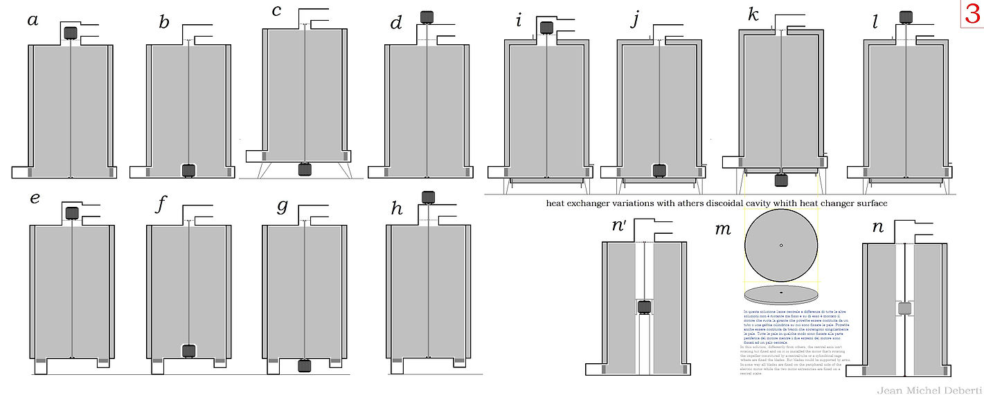


Table 19 : Study-attempt to design heat exchangers for recovering heat from hot and dirty fluids such as industrial fumes from which to try to confine the dust instead of throwing it completely into the atmosphere, fig E6-E7, and possibly, in the absence of other uses, eliminate it by burning it after compacting it.
Table 20: Study on how to transform the casing of centrifugal pumps into a heat exchange surface transforming them also into heat exchangers.
Table 21 : Another kinetic efficiency study on possible scroll shapes for the air outlet environment of the impeller in dynamic cylindrical cavity heat exchangers.
Table 22 : Studies of insert shapes for cylindrical or conical cavities of dynamic heat exchangers in which air or water flows into the impeller environment.
Table 23 : Studies for discoidal and conical heat exchanger cavities for dynamic water-water heat exchangers with centrifugal pump function.
Table 24 : Studies of dynamic heat exchangers with a centrifugal fan function with two concentric cylindrical and conical cavities considering the effects of slowing down the crossing velocity of a heat exchanger when the crossing sections expand. For example, if the air exiting the exchanger does not need to be channeled but can be discharged into the environment with the lowest possible speed and pressure.
Table 25 and 26 : Studies of dynamic, internally hollow, cylindrical cavity heat exchangers for heat exchange between air and water/refrigerant fluid, to reserve internal space for equipment and components of heat pump systems or other.
Table 27 and 28a : Studies of dynamic, internally hollow, cylindrical heat exchangers for heat exchange with air, with concentric cylindrical cavities arranged at scalar heights.
Table 28b : Small external air-conditioning unit, consisting of a dynamic heat exchanger with multiple concentric cylindrical cavities.
Table 29 and 30 : Heat recovery from stale air and immediate heat transfer to fresh air for large shopping centre environments. These are dynamic air-to-air heat exchangers for vertical or horizontal installation.
Table 31 : Study of hydraulic circuits for geothermal heat pumps interacting with well water, i.e. groundwater water or underground water courses called veins of water.
Table 32 : Study of interior of cylindrical cavity for evaporative function only, for vertical positioning, swept on one side for evaporation of refrigerant fluid in the usual manner but trying to avoid liquid heights that may generate significant hydrostatic pressure and delay in the rise of vapour bubbles.
Table 33 : Another study of a hollow dynamic exchanger with a single cylindrical evaporative cavity for vertical positioning, swept on one side only and facilitated evaporation. The figure shows that, in the case of a well water geothermal heat pump system, the reservoir and other components can all be placed inside the exchanger.
Table 34 : Still evaporative heat exchange cavities. Figures A and D1 are those with a single-sided cylindrical heat exchange surface in which spiral or circle elements internally retain the liquid refrigerant on the heat exchange surface, but as can be seen from Figures E1, E1', N and O , they can be made so that both surfaces of the cavity are heat exchange surfaces. Figures F, G and G' use a hygroscopic layer to retain the liquid refrigerant on the heat exchange surface, but these solutions, while requiring little operating energy, have a higher thermal resistance to heat flow penetration because the liquid in the hygroscopic layer moves too slowly. H, I, I' solutions, on the other hand, have spray nozzles to wet the heat exchange surfaces with liquid refrigerant. Figures J, on the other hand, involve using a tubular spiral to release the liquid refrigerant to be evaporated at the base of the cavity and allow it to evaporate by flowing through the space between the spiral coils and the cylindrical surfaces enclosing it. Or, in the condenser function, with application of the new condensation process, the exchanger environment will be totally flooded, and the vapour to be condensed will be introduced into the spiral tube, via an injector, together with the recirculation liquid. Figures J1',J2',J3',J4' indicate that, with the use of a spiral tube inside the cylindrical cavity, an upside-down operating position is also possible compared to those shown. Figure K, as an alternative to rings, shows the possibility of using a spiral strip made of a special profile to hold the liquid on the heat exchanger surface and in which the refrigerant can descend as in a chute to the base of the heat exchanger.
Table 35 : Yet another type of heat exchange surface for rotary dynamic heat exchangers. In fact, it consists of the surface of a cylindrical spiral of pipe inside a cylindrical surface. In the cases illustrated, the rotation of the impeller pushes the air to screw into the space between the coils of the spiral and the surface of the cylinder, up to the outlet area which can be realized carefully, to producing an additional head, or have a simple exit conduct.
This heat exchanger allows heat exchange non only with air but also with a joint use of outside air and well water for partial geothermal use, or by closing the air inlet, heat exchange takes place with well water only with the inside of the impeller environment, occupied by water only partially. If the blades come close enough to the spiral and the impeller rotates fast enough, then even a liquid can be pushed into the space between the coils and even dragged upwards. This subjects the liquid to an even faster flow of gas or steam, enhancing the phenomenon of evaporation provided that the gas or vapour is not saturated, meaning it does not have the maximum degree of relative humidity. This happens in Figures J3 and J5 where, respectively, refrigerant or water is pushed by the rotation of the impeller up to the separator from where it falls back towards the inlet. The environment of the impeller is sealed from the outside in the case of figure J3 in order to keep the refrigerant at operating pressure conditions, while it is open to the passage of air in the case of figure J5 because the partial evaporation of water in the air lowers the temperature of the water allowing better cooling of the refrigerant flowing in the spiral. For this reason, the provision of water can be beneficial even if moderate; however, it should be noted that, in the case of water, the flow must be sufficient to prevent the non-evaporated water from reaching an overly high saline concentration that would allow it to carry with it, in solution, the salts left behind, as residue, by the evaporated water.
Note that the liquid level in the separator in Figure I1 is regulated by the position of the liquid refrigerant outlet duct so that the excess vapour is led back into the evaporator.
Table 36 : In this case something similar to a cylindrical cavity is realised with a stack of several round elements. A tube runs straight through the whole stack to the bottom of the last round element. In operation as an evaporator, liquid refrigerant is released through this tube to be evaporated at the bottom of the last round element in the stack, from where it rises towards the summit while a part of it transforms into steam, while the operation as a condenser is possible both in the classic mode and with the new process. In the classic, usual mode, the vapour is introduced under pressure and the condensate, poured into the lowest round element, flows up the tube due to the pressure difference between the inside of the condenser and the rest of the circuit. With the new condensation process, however, recirculating liquid and condensing vapour exit this tube together and the vapour bubbles, dispersed in the liquid, condense as they rise up the stack. There is an important issue to take into account. This is the case with a compression heat pump system with the ability to manage the amount of refrigerant circulating in the system by confining a part of it in a special tank, in order to feed it back into the system when needed. There may be an eventuality of too low a refrigerant level in the separator, caused for example by excessive vapour production. This, in the case of the new condensation process, could stop the recirculation of liquid refrigerant through the condenser, stopping or slowing down the condensation of refrigerant vapour to a standstill. If the connection to the evaporator located at the overflow in the separator in figure I is not sufficient, figure J shows that a connection circuit between the separator and the compressor suction could be used so that, by removing pressure from the separator, the liquid level rises again.
Table 37 : In this table, this air-water or air-fluid heat exchanger with a cylindrical spiral no longer has the spiral with spaced coils and leaning against a cylinder as seen in the previous table, but this time, the spiral is made with the coils tightly wound, so that there is no space between them, because this allows the air flow to lap against it, on both sides and no longer only on the inner side, as seen previously. To give solidity to this more complex form of impeller, it is encased in a cylindrical outer casing, the same as that already shown for the heat exchangers illustrated in Tables 9 and 13.
Table 38 : Cylindrical surfaces such as those of a spiral have larger exchange surfaces if they are large in diameter, but for liquid fluids, running in large-diameter pipes means running too far from the heat exchange surface and this is solved by inserting another concentric pipe or a space-filling form in the centre of the spiral. The filler tube form inserted in the spiral of the heat exchangers shown in this table, have a narrow central duct in which, in the new condensation mode and in the traditional evaporation mode, the liquid refrigerant flows to the bottom of the spiral from which it then rises to the heat exchange surface. Spiral turbulators can be used to distance the spiral tube from the inner tube or filler tube form.
Table 39 : Further explanations on how to make heat exchangers with cylindrical cavities and descriptions of their internal zig-zag labyrinth inserts particularly suitable for heat exchangers working in a horizontal position.
Table 40 : Single-unit air conditioner shown installed on the balcony of a building. It consists of two concentric cylindrical cavity heat exchangers and components including the impeller motor, compressor and expansion valve. Various ways of realising the unit are illustrated.
Table 41 : In these examples, we show the possibility of using a single, special impeller to simultaneously sweep the surface of both the concentric cylindrical cavities that function as an evaporator and those that function as a condenser. The cavities with different functions are fixed at opposite ends of the heat exchanger. The impeller is divided internally by a layer of thermal insulation.
Table 42 : Beautiful monobloc heat pumps to be realised in large sizes. The heat exchangers acting as evaporator and condenser are the simplest dynamic rotary heat exchangers imaginable because they have the heat exchange surface consisting of just a single, simple cylindrical surface swept by one impeller on the inner side and one on the outer side, and these two impellers are coaxial and can be joined together, i.e. they can be joined and rotate in unison. These compression heat pumps, use the new evaporation process, the description of which has already been mentioned in Table 1, while the condensation process used, can perhaps be defined as the classic process of strengthening by means of a rotating impeller, which drags the vapour stream over the heat exchange walls. Therefore, neither the evaporation nor the condensation process takes place in these heat pumps in the ordinary manner, as both the evaporation and condensation processes take place in an environment in which the liquid refrigerant appears as a thin layer spread over the surface of the heat exchange surface therefore the liquid refrigerant occupies a very small part of the volume of the room in which evaporation and condensation take place. In such conditions, evaporation does not only occur as boiling, but also as a transition, a dispersion in a gas or vapour, which, however, does not have to be in a saturated condition, as in the case of clothes hanging out to dry in the wind when the air is not too humid. In that case evaporation occurs even at low temperatures and from time to time, I try to reproduce this effect in heat pumps because it would be revolutionary but I have not yet found the way, perhaps because, I tell myself, in nature at least condensation occurs when it is colder or when the relative humidity exceeds the maximum value. However, I am not a salaried researcher and as I have not found anyone who would offer me an agreement or employment, I cannot continue, unless the publication of the rest of my work in this second part of this site, will change something.
Table 43 : Heat pumps with two different types of heat exchangers are described. The inner one is a heat exchanger that has a single cylindrical surface for heat exchange, and the outer one is a cylindrical cavity. Since refrigerant vapor is also present in the internal environment of the first heat exchanger, therefore being under pressure, to avoid creating a weak point in the casing of the internal heat exchanger, a separate motor is preferred for the internal impeller of this heat exchanger, while the second impeller, separated internally by thermal insulation, sweeps both the cylindrical cavity and the outer surface of the inner heat exchanger. In the figures, the fixed parts of the machine are outlined in black while the impeller contains a cylinder inside, in violet, equipped with thermal insulation per impedire un flusso di calore tra il condensatore caldo e l'evaporatore, freddo. By keeping such large impellers rotating, is requires them to be non-deformable and suspended with bearings, especially if they rotate horizontally. When the appliance is designed to operate in a horizontal position and when the inner heat exchanger, is operating as an evaporator, it is sufficient to drop the liquid refrigerant onto the internal surface of its cylinder. When the appliance is designed to operate in a vertical position, the liquid refrigerant can be sprayed onto the cylindrical surface from the hollow part of the impeller's axis of rotation, as shown in figure I. As these units are to be connected to a ventilation system, Figures L and K indicate that instead of reversing the condenser-evaporator functions, four-way valves can be used for ventilation to divert the hot and cold air flows to the outside or to the inside depending on whether heating or cooling is intended.
Table 44 : Still large monoblock heat pump units, but this time the heat exchange surface consists of a deep circular concenric grooves, centred on a circular plate. The grooves are, however, in this case, so deep that it is not made by pressure deformation from a flat plate, but are several flat, cylindrical parts welded together. The innermost impeller has a cylinder centered on the axis of rotation, and this cylinder rotates within the circular groove of the exchange surface so that the fluid, in order to pass over this cylinder, must reach the bottom of the circular groove. A second impeller, coaxial but not in contact with the first, sweeps the other side of the circular groove surface, and the figures on the right side of the table illustrate this situation well even in the case of multiple concentric grooves in the heat exchange surface. The heat exchange surface, as with other heat exchangers, isolates the environment through which the air passes from the sealed environment in which the refrigerant is enclosed. Two of these heat exchangers, here imagined overlapping rather than side by side, form the heat pump.
Table 45 : In the same way that a heat exchanger whose heat exchange surface consist in a single cylindrical metal sheet but, this time the heat exchange surface consists of a cone. The circulation of the refrigerant steam flow through the machine, directed towards the heat exchange surface by a filling shape fixed between the impeller blades. In the evaporator function, the centrifugal force induced by the thrust of the rotating blades pushes the refrigerant liquid up the inclined surface of the cone, and this also happens in the condenser function to the refrigerant liquid generated by the condensation of refrigerant vapour. There are two separate motors, one for the inner impeller confined to the sealed area of the heat exchanger, the other is located in the outer area and rotates the outer impeller. This avoids a single shared axis of rotation around which a seal joint could become loose, causing pressure and refrigerant leakage from the sealed part. Reversing the heating and cooling cycles is possible, and for the simplicity of not having to draw the whole circuit with the four-way reverse cycle valve, one pretends to be able to reverse the compressor action.
Table 46 : These are examples of the possible positioning of one or more electric motors moving the impellers within the heat pump system seen above.
Table 47 : In figure A Simple but bulky geothermal plant made with the simplest single-cylindrical cavity heat exchangers swept by the impeller on the only inner side already seen in figure 1 and in which, in two of the heat exchangers, the refrigerant occupies the space of the impeller while the water flows in the cylindrical cavities. There is then a water storage tank and a third heat exchanger, of the same type, which serves the domestic ventilation system.
In Figures B and B', the same system is reduced to just two units by means of more complex cavity heat exchangers. It operates using the new evaporation process and the usual condensation process but enhanced by the fact that the impeller rotates the vap our on the heat exchange surfaces intensifying the thermal exchange.
Table 48 : Hydronic heat pump monoblock unit with reversible heating and cooling functions. I explain once again that, for descriptive simplicity, in all this work, I did non draw the circuit othe flow reversal valve pretending to be able to reverse the flow on the compressor. It works by using the new evaporation process and the usual condensation process but enhanced by the fact that the impeller rotates the steam on the heat exchange surfaces. The heat exchange elements of each exchanger are two cylindrical cavities arranged in an alternating position in which the water flows through the cylindrical cavities while the refrigerant is confined to the space occupied by the impeller.
Table 49 : Hydronic heat pump monoblock unit with reversible heating and cooling functions. It operates using the new evaporation process and the usual condensation process but enhanced by the fact that the impeller rotates the steam on the heat exchange surfaces. Unlike the previous device, it has non simply three concentric cylindrical cavities, but they are arranged on the same side, but like the previous device, the water flows through the cylindrical cavities while the refrigerant is confined to the space occupied by the impeller.
Table 50 : Packaged heat pump air-conditioning units but the heating and cooling functions that can be connected to ventilation systems are not reversible inside the device and could only changed by inverting the inlet-outlet air positions. Equipped with air-cooling heat exchangers, unlike the two previous devices, the heat exchange elements are not the type of concentric cavities, but consist of two surfaces with concentric circular grooves. They operate using the new evaporation process and the usual condensation process but enhanced by the fact that the impeller rotates the steam on the heat exchange surfaces. They can be manufactured in small sizes, to serve a single flat, or in medium or large sizes. There are two pipes in the circuit, one connected to the bottom of the evaporator and removes any liquid that may not have been evaporated, which can happen if the thermal power demand is increased. The second pipe removes the refrigerant liquid condensed in the condenser. This does not require a small pump to remove the liquid due to the head produced by the rotation of the heat exchanger impeller.
Table 51 : Still air conditioners with reversible heating and cooling function with heat exchange elements consist of a surface with concentric circular grooves. It operates using the new evaporation process and the usual condensation process but enhanced by the fact that the impeller rotates the steam on the heat exchange surfaces. Funziona utilizzando il nuovo processo di evaporazione e il processo di condensazione usuale ma potenziato dal fatto che la girante fa ruotare il vapore sulle superfici di scambio termico. The circuit, different from the previous one, contains two expansion valves and two non return check valves.
Table 52 : Packaged air conditioner with reversible heating and cooling function with heat exchange elements consisting of cones inserted into each other like paper cups. It operates using the new evaporation process and the usual condensation process but enhanced by the fact that the impeller rotates the vapour on the heat exchange surfaces.
Table 53 : When both a liquid and a gas are present inside the environment of the impeller of this heat exchanger, the rapid rotation of the impeller, due to centrifugal force, keeps the liquid out of it and therefore in the space between the turns of the spiral that surrounds the impeller.
We have seen how a cylindrical spiral with tightly wound coils can essentially be equated with a cylindrical cavity having a spiral as its inner insert. A spiral with equidistant coils against a cylindrical surface, on the other hand, is a different matter because of the effect created when the rotation of the internal impeller forces a gaseous or a liquid fluid to travel through the space between the coils like a screwing inside a thread, possibly causing even the circulation of a liquid in a eventual recirculation circuit outside the exchanger without the need for a pump. We have also seen that the gaseous fluid in the impeller environment can generally be air or refrigerant steam. In the case of air, the environment of the impeller is traversed by the flow of air and the exchanger can also behave like a centrifugal fan, producing the head that promotes this flow of air. In the case of the refrigerant, on the other hand, the environment of the impeller is sealed and the rotation of the impeller serves almost exclusively to retain between the turns, the refrigerant liquid that has condensed or is to be evaporated while it is invested by a fast current of vapour. When the impeller is large, there is a need for a system to slow down the revolutions of a motor by increasing the copy.
Figure F depicts a heat pump based on this type of heat exchanger in which the heat exchanger on the left is operating as a condenser using the new condensation process while the one on the right is operating as an evaporator partially using the new evaporation process, partially because the liquid state, in this case, is not a thin layer.
Table 54 : The appliances described in this table are not true heat exchangers but, especially when supplied with fresh water, it would be more correct to call them air coolers. The cooling capacity does not depend solely on the temperature of the water but on the fact that as it evaporates it absorbs heat from the air, cooling it but also making it more humid. In order for a cooler to perform its function, it needs the air to be far from saturation conditions, i.e. the relative humidity to be far from 100%, because then evaporation of water at a temperature lower than boiling cannot occur, and in such a case, the only way for a cooler to work is if the water is cold enough and in sufficient quantity to absorb the heat from the air. However, one should not think that a cooler brings the maximum level of humidity in the air, because the air reaches its minimum temperature in the cooler, and when it exits and warms up, the level of its relative humidity at the new temperature, decreases. Although a cooler requires less energy than a heat pump, it has the disadvantage of making the air more humid. Today's coolers work on the basis of hygroscopic surfaces that let air pass through, the one presented here instead makes water adhere to a cylindrical surface by means of centrifugal force. If sufficiently cold brackish water is used, it will release less moisture into the air due to its hygroscopic power. It should also be borne in mind that in the case of the coolers shown, the metal surfaces act as a catalyst because once cooled by contact with water, they participate in absorbing heat from the air.
Table 55 : More coolers, some with conical rather than cylindrical surfaces.
Table 56 : Illustration of a compact wall-mounted cooler. Note that there are concentric cylindrical surfaces on both, the base and the rotor, pushing air and water from the centre to the periphery from where the water is separated from the air by passing through a separator.


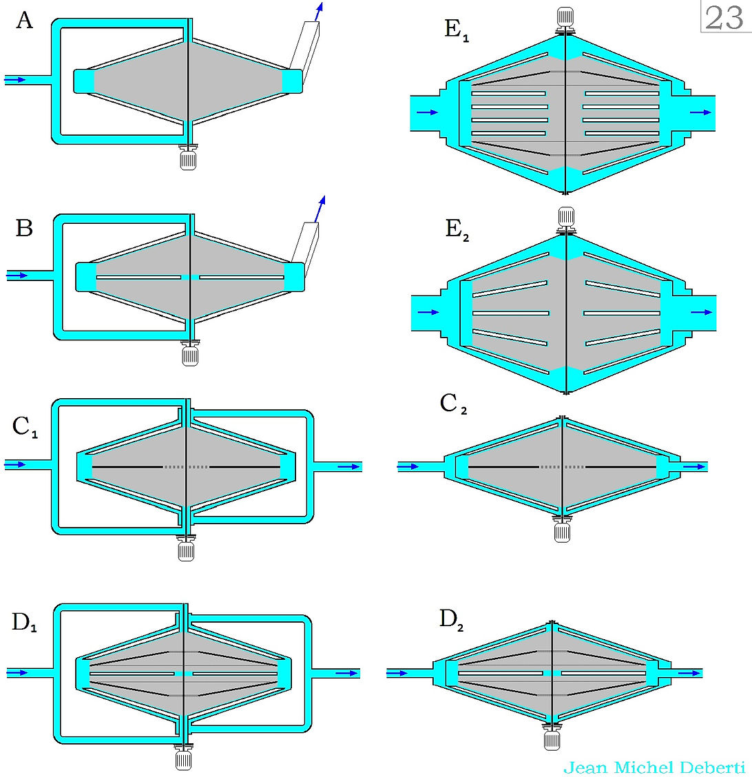


Table 57 : This time here are heat exchangers with flat or nearly flat cavities which, like cylindrical ones, have an internal insert to create an orderly path for the internal fluid. As in the case of cylindrical cavities, the insert may be zig-zag shaped resembling a labyrinth, or a flat spiral or several flat spirals placed one between the coils of the other. If the exchange elements are flat cavities, placed parallel and superimposed, the impeller, which passes through the central part of these cavities, also consists of several arms placed in parallel and superimposed planes and each blade resembles a comb. Figure D shows a monoblock air conditioning that is compact and thin enough to fit even under a window. Figure H shows us how these air-cooling or water exchangers can extend to the surface while remaining fairly flat. As heat pumps, in heating function, in really cold places, they would be facilitated in getting rid of ice formation on heat exchange surfaces because lacking heat diffusion fins, like those in fin-tube heat exchangers, it has a smooth surface with no grips for ice and therefore defrosting would be less frequent and faster. Today, at 5°C air temperature, 80% is a normal value of relative humidity and in this condition, defrosting takes place 2 or 3 times per hour, lasting 10 minutes each time, meaning that, in these conditions, the appliance defrosts almost half the time it is heating, I let you only imagine what is the real efficiency of the appliances value in these conditions and how important would be to change this one.
Table 58 : Figure A is more of a digression. It suggests a low-energy application of heat exchange between a well on a vein of water whose depth of water draught is less than 7 metres in relation to the heat exchanger. it suggests, by giving more power to a pump, raising the water level until it totally occupies a reservoir at the top by letting the air out. Then, when the tank is closed, a vacuum is created in the water line that keeps it from going down into the well. At this point, with minimal power, the water is circulated between the well and the exchanger as if they were at the same level until the gases that are normally dissolved in the water and some steam cause the water level in the tank to drop again.
[[ I would like to remind you that the position and depth of water veins was discovered in ancient times with the help of a dowser who used a wooden or metal fork that, under tension, aimed at the source, caused involuntary movements of the muscles causing it to rotate, and this is not an invention because I am capable of it myself, having been taught by my passionate engineer father. They are simply perceived by some people as unevenness of the surface magnetic field caused, over a period of about 50 years, by substances such as water, vacuum and some metals and alloys due to their different magnetic permeability with the surrounding ground. We no longer look for veins of water because of underground sewage pits and extensive fertiliser use that has contaminated surface water that is no longer drinkable. Animals sense the presence of water more easily than we do. ]]
From figure B, a
HEATING METHOD FOR SOLAR THERMAL AIR FLOW APPLICATION The best way to realise an air flow solar thermal system is to use a water storage tank with an internal air-water exchanger to immediately pass the heat from the hot air flow produced by the system to the water in the tank so that it can be reused later only for hot water production or to pour the heat stored in the tank water back into the air of the ventilation system. Those shown are tanks with an air-water heat exchanger different from those already shown in the patent application 'Cylindrical Helix Heat Exchangers with Three Concentric Tubes' described in the first part of this site. The proposed system consists, in its basic form, of an air flow solar thermal panel cover (of which, some forms will be proposed later, with high efficiency, of which, I am not aware, prior patents, but to be on the safe side, I say again, you will have to check first for any prior patenting, I do not do this because my intention is, at the moment, only informative), water storage tanks with the function of thermal accumulator and, possibly, domestic hot water production, and possibly, a special compressor of my own invention that serves to raise the temperature of the air by compressing it if the required temperature difference with the water in the tank is not being reached.
Figure B . The heat exchange element consists of a cylindrical cavity (c). In order to direct the tank water with a certain velocity onto the heat exchange surface (c), a cylinder (e) is placed at a certain distance from it. The cylindrical cavity (c) is kept at a distance from the tank surface (a) and the cylinder (e) by the cylindrical helix spirals (b) and (d) between whose coils the tank water is circulated by means of a pump. The figures show how this is achieved. The figures between D and H3, on the other hand, are storage tanks with exchanger acting as condenser for a heat pump system. Figure L . This is a compressor with two pistons, both joined by the same axis and two cylinders, one large and one small. The thrust system has deliberately not been included because it can be done in various ways. The idea is to try to recover as much of the energy used in compressing a gas in a heat exchanger as possible when that gas leaves the exchanger to return to its initial pressure. But the gas when it exits is compressed, so to recover at least part of the energy from the same quantity of the refrigerant that was compressed, which therefore lies in a smaller volume according to the law P1xV1=P2xV2. It is an isothermal transformation because the outgoing air has cooled down while passing through the heat exchanger and has the same temperature as when it entered. P2 is the pressure reached inside the heat exchanger, and V2 and V1 must be such that the mass of air that exits is the same as that which enters, in order to maintain a constant pressure inside the heat exchanger.
If P2>P1 then V2<V1 i.e. if in the large cylinder the volume expands to V1, in the small cylinder the maximum volume attainable is V2. When the outgoing compressed air enters the small volume, the piston is assisted in its ascent, allowing to save some of the energy required for the compression. Figure M is a diagram of how such a system could be done, in blue is drawn the alternative path for the air flow when it is still warm enough not to need to be heated by compression. The piston compressor in fig. L is equipped with 8 non-return valves, but an energy recovery centrifugal compressor, that does not require valves, has already been described. Using this type of compressor, which does not require the use of expansion valves, is equivalent to using the Joule-Brayton cycle, but its use in heat pumps where the volume of steam collapses due to the change to a liquid state, is no longer as interesting.
Table 58b : Example of an air flow solar thermal system with a storage tank and an internal air-water heat exchanger. The scheme is so simple that a single diverter valve determines whether the air flows between the panels and the tank or between the internal air intake and the ventilation system in the ceiling, passing through the exchanger inside the tank or partially through both paths.
Note that the heat exchangers equipping the water storage tanks shown in these last two tables consist of a spiral of pipe clamped between two cylindrical surfaces, one of which constitutes the tank wall. In this way, the flow of water is forced to follow the path between the coils, lapping the thermal surface of the spiral at a speed that is essential for more effective heat exchange.
It can either be realised with the spiral inside the tank, in which case the spiral must be inserted externally against the inner cylinder before closing the tank, or it can be realised with the spiral outside the tank, in which case the spiral must be placed against the already closed tank and enclosed in a cylindrical container clamped to it and closed at both ends. The pictures on the right side mean that the circular tube shape as a section of the spiral is the easiest to make, but there are shapes of sections that are more suitable for heat transfer.
Table 59 : These are giant heat pump exchangers whose heat exchange takes place through a single cylindrical surface. It is an heat exchange between refrigerant fluid and air with the presence of water. There are two aligned impellers, one internal and one external to the cylindrical exchange surface, and they are so large (and I do not know if this will ever be realised) that they require bearings (not always shown) to keep them rotating without bumping into fixed parts. Even in this case, the environment in which the refrigerant is present can be either that occupied by the central impeller or the environment occupied by the peripheral one, and the refrigerant or water can be sprayed onto the heat exchange surface from nozzles placed on the rotation axis.
Table 60 A: SOLAR THERMAL AIR FLOW. This topic deserves a serious discussion because the current thermal solar panels are aesthetically pleasing but, in my opinion, quite inefficient because they are technically too simple and not imaginative enough. The first two figures show two different ways of constructing a type of air flow solar panel, where the collecting surface is glued to the glass and in the space between the glass and the light-collecting surface, the air is replaced by more insulating argon gas. There are two ways to create this type of solar panel depending on whether the gaseous atmosphere of argon is rarefied, that is to say in depression, or in slight overpressure compared to atmospheric local pressure on the ground. This enhances, compared to simple air, the greenhouse effect due to the gaseous layer and the fact that the airflow touches every point of the overlying capturing surface, can immediately remove the heat from the point where it appears, without having to travel across the capturing surface to a pipe of the collector located beneath it, as is the case with today's water-based thermal solar panels. [ It would be different for water solar panels if the capturing surface were made up of a single sheet of blackened pillow plates heat exchanger (PPHE), permanently fixed to the glass by a silicone frame with an argon atmosphere between the glass and the capturing surface, but I don't know if anyone has ever made them that way. If a manufacturer grasped the idea, I would advise him to print an orderly path for the water inside the pillow plate collector as suggested by what is in the drawings that follow, because it avoids points of water stagnation while ensuring a certain flow velocity, which promotes heat absorption. However, if the pillow plate were to be made of very thin metal, to be fed with low-pressure water, it would be advisable to use a closed circuit with an open tank, with a circulation pump and connected to a heat exchanger.]
Table 60 : When striving for efficiency in solar thermal panels, one must follow rules that are poorly followed in today's water-flow solar thermal panels, with the result that they are not only inefficient but also expensive, while many of the air-flow solar thermal panels, are made to ridiculous standards.1° When the surface of a panel heats up under the sun, this heat must be transferred quickly, otherwise a good part of it get lost; and to avoid this one, the heat transfer fluid must flow under every point of the light-capturing surface.2° In thermal solar panels, a greenhouse effect is relied upon, which corresponds to a kind of transparent thermal insulator. No insulator is completely insulating; there are various degrees of insulation, and in the field of advanced double glazing, there has been a shift from using simple dried air, to gases like argon, krypton, or to vacuum. It is not advisable to use double glazing on a solar panel due to the reflection and diffraction phenomena of light on the glass, phenomena that, in the case of double glazing, are repeated in the second pane as well.In a traditional solar thermal panel, behind the absorbing surface, there is usually a bundle of parallel tubes connected at each end by a collector, or, less commonly, there may be a single tube bent several times in a zig-zag pattern, fig. A16. The collector lies on a bed of insulation while a thin copper sheet, dyed black at the top, covers it. The light striking the sheet must pass through it to the point below which the copper tube is located. Although copper is a good conductor of heat, it also offers thermal resistance, especially if it is a thin sheet and heat transfer is not immediate, which, as mentioned, causes some of the captured heat to be lost. In addition, even a small contact surface between the slab and the pipe results in thermal resistance. Moreover, only along lines near the collector pipes is the plate temperature lower, while it gradually increases at other points, which causes more heat to be dissipated. Bringing cooling water under the entire slab surface creates problems because water is incompressible and a failure of the pressure regulation system and filling the system could easily burst or deform them. If you want to cool the capturing surface evenly, air is the easiest way. In addition, since it has a much lower calorific value than water, it must be sent in a much faster flow and this, with the same average temperature of the parts, could make heat exchange take place more effectively. Krypton is a gas with a remarkable price and, in double glazing, it is technically more advantageous than argon only with gas layers less than 12 mm, a measurement that is easily exceeded in thermal solar panels. The panels shown provide at least two possibilities. The first is to attach a frame made of an elastic material like silicone to the edges of the cover glass, which can absorb the different thermal expansion, and to which a rigid or semi-rigid sheet of copper or aluminum can be attached. Support elements or a spacer grid made of low thermal conductivity material, resistant to UV rays and heat, and with a rounded surface to limit contact, must be placed under the slab to support it. An argon atmosphere in slight depression relative to atmospheric pressure will create a force that will keep the sheet pressed against the glass and resting against the spacers. the rarefied argon atmosphere serves two purposes. The increase in temperature due to solar exposure would increase the pressure of the gas under the sheet, but even with thermal expansion, the gas would still have to remain in a slight depressionin in order to maintain a push of the light-capturing plate towards the cover glass. Furthermore, a rarefied argon atmosphere has less thermal conductivity than an the same at atmospheric pressure. The absorbing sheet can be simply black or even photovoltaic.The glass and the capturing surface joined together, thus form a single piece. Inside the case on which the glass and the absorbing surface are embedded and fixed, there is a pathway that can be in the shape of a single flat spiral, Figure A13, or a double flat spiral, Figure A14, in the shape of a rectangle, which acts as a pathway for the air flowing under the absorbing surface of the panel with an air inlet and an air outlet point. This air path under the absorbing surface can also be collector-shaped, Figures A9, A10, or zig-zag-shaped, Figures A11, A12, or labyrinth-shaped, Figures A15. There is another way to create this solar panel, which is by fixing a thin and flexible metal capturing surface to the glass, possibly reinforced with some fiber or heat-resistant plastic. In this case, to prevent the flexible capturing surface from adhering to the glass, the gas atmosphere inside is just above atmospheric pressure, and what keeps it from inflating like a balloon is the fact that it is held back by the edges of the walls of the airflow path inside the panel's casing or by a rigid metal mesh rested at the ends of the air path in the panel. This overpressure also serves to compensate for the reduction in gas pressure on cold winter days. Given the thinness and flexibility of the capturing surface, this solution does not present problems of different thermal expansion with the glass sheet to which it is attached. Obviously, even in this case the absorbing surface is blackened in the part exposed to light. There is yet another way of realising this panel, and that is by fixing not an opaque absorbing surface under the glass, but just a transparent plastic material such that, like glass, it does not present high reflection or diffraction problems. In this case, it is the inside of the air path in the panel case that is dyed black to absorb light and the gaseous plastic bag acts as a thermal insulator. Please note that the same solar panels can be integral parts of the roof. In this case, a cover is prepared on a roof without tiles for the air flow, which will then be covered with glass panes to which the capturing surface has been fixed in the manner described. The flow of warm air heated by the sun must be fed into a water storage tank equipped with an internal air-water heat exchanger. This heat-exchanger tank will be of a type that can interact with a ventilation system or a hydronic radiant heating system and can also be powered by a hydronic heat pump, in the many ways described starting from the first part of this site. Fig. A18 shows what, in my opinion, is perhaps the only intelligent airflow solar thermal panel solution in existence because the use of inverted U-profiles to make the capturing surface helps conduct heat deep into the air stream. Figures A 20, 21, 22 show what the capturing elements of today's vacuum-insulated water flow solar panels look like. Efficient but expensive. Fig A22 is an idea of an air flow or water flow variant in this sense. Fig A23 is an example of an air flow solar panel that can be easily realised by anyone, the issue is that in a complex system, you need a storage tank with an internal air-water exchanger. The problem related to rigid capturing surfaces is that they are made of metal, which has a different coefficient of expansion than the glass of the panel. If they are joined together, with different cycles of heating and cooling, it can lead to breakage. Therefore, the insertion of a thick frame made of elastic adhesive material like silicone, can absorb these differences. The figures in box B relate to the study of rigid capturing surfaces for both hydronic and airflow solar panels. Figure B22 assumes a deep-drawn surface in order to absorb, through a very slight bending of its reliefs, thermal expansion and the use of small spheres as spacers both for the possibility of movement and the modest support section to the glass, while the 7th figure in this box proposes a surface with crossed undulations from two orthogonal directions in order to absorb, through deformation, expansion from each direction and to give rise to a surface that generates turbulence in the air flow that laps it so as to improve thermal transmission. The weak point of this solution is still the edge, which, if straight, forms a frame that expands or contracts thermally as we do not want it to. This means that we should fit the edge into a resin frame while preserving all the undulations of the surface and paste this frame on the glass. Box C illustrates ideas for making inflatable solar panels to heat agricultural greenhouses. All the parts, including the transparent ones, are made of flexible plastic, and it is simply proposed to improve the greenhouse effect by injecting argon into the environment bounded by the transparent plastic upper shell and the capturing surface, also made of flexible material, under which, the air flow to be heated.Box E describes an airflow solar thermal panel with a low visual impact. It is narrow and long so that it rises slightly from the roof surface and is therefore less visible from below. This panel consists of a semi-cylindrical, internally thermally insulated body, with a diameter of approximately 20 to 60 cm and is mounted in parallel rows on its support. The suppot structure of these panels also provides the function of single axis solar tacker, allowing it to change inclination to be perpendicular to the plane of the solar rays. The internal air path can be very simple because, if the diameter is small, the air flow only touches the heat exchange surface once, in a single direction or, if it is wide enough, the internal air pathway can be divided into two parts so that the flow, having reached one end of the panel, can return back along the other part.
Table 60b : This is a middle way between a concentrating solar collector (those in which a mirror converges light onto a small surface) and a flat solar panel. It can be internally insulated with a rarefied argon gas atmosphere, and the ease of sealing is enhanced by the fact that the light-capturing part is a black tube through which air flows, which is free to expand or contract itselves inside the panel because the only constraint between the capturing tube and the panel are the inlet and outlet ducts, both aligned with each other. The problem with these panels is that, to work well, they must be oriented towards the height of the sun on the horizon and require a blue sky without cloud cover and this condition is common only in countries like Australia.
Table 61 : Examples of simple systems with solar panels both for water flow and air flow, with a storage tank and a heat exchanger (dr = dynamic rotating) air-water. But above all, there are examples of systems with evaporative solar panels, my first Italian patent from 2008 which has expired. Fig. I is just a mental speculation, the idea is to place a heat exchanger around and inside as a casing for the energy-recovery centrifugal compressor and to use it in an alternative solar heat pump system yet to be defined, in which a refrigerant fluid is dissolved in another gas not intended for condensation. I could imagine that these fluids could be an atmosphere of helium and ammonia or a solution of water and ammonia.
Table 62 : The shape of dr heat exchangers is imitated in small scale to make for electronic components.
Table 63 : To prevent fires, here is the idea of placing the electronic circuits in a closed box in which there is inert gas and in which a thermal exchange with the outside air takes place via a small, conical, air-to-air dr heat exchanger. In addition, considerations on dr heat exchangers with a heat exchange element consisting of a cylindrical cavity that instead of being swept by the impeller blades on the outer side only, a spiral is placed on this to direct the flow of air leaving the exchanger on that side of the cavity. Fig. J , when air and water are used together in the heat exchange, for example with refrigerant, surfaces with circular or threaded grooves would help to retain the water and increase the heat exchange surface.
Table 64 : This time, the heat exchange elements consist of spirals of pipe with a small diameter. Flat circular spirals that are also repeated in several parallel planes, or double-cone spirals, i.e. hourglass or rhomboid-shaped spirals with the impellers sweeping the surfaces from the inside while the outer casing of the exchanger also encloses the impeller and rotates with it, directing the air flows moved by the impeller onto these pipe spirals.
Table 65 : More examples of large air-to-air exchangers with the function of heat recovery or fresh air from stale air before it is expelled to the outside.
Table 66 : Figures A,B,C studies for hollow air to water or refrigerant fluid heat exchangers with heat exchange elements consisting of cylindrical cavities and designed for operation in a horizontal position. Fig. D and E, gas heaters for ventilation systems made from air-to-air dr heat exchangers with heat exchange elements consisting of a single cylinder. Fig. F steam generator realised from an air-to-air dr heat exchanger with a heat exchange element consisting of a single cylinder. Fig. G and G' , steam generator realised from an air-to-water dr heat exchanger with a cylindrical cavity. Fig. D' boiler with storage tank for heating ventilation air realised from a dr heat exchanger. Fig. H boiler realised from a cylindrical cavity dr heat exchanger. Fig. E' , hot-air heater for ventilation system manufactured from a dr heat exchanger whose heat exchange element consists of a metal cylinder. Figs. I and I', compact hot-air heater for ventilation system produced from a heat exchanger dr whose heat exchange element consists of a surface with circular grooves. Fig. J appliance with two functions, gas stove + heat pump. Consisting of three superimposed dr dr heat exchangers of the heat exchange surface type consisting of concentric circular grooves. The small motors rotating the impeller inside the areas crossed by the refrigerant, are encapsulated to prevent leakage at the points crossed by their axis of rotation. Fig. K is still a heat pump and, even with this type of heat exchanger, heat exchange with well water can be carried out at the same time as the air to further improve energy efficiency.
Table 67a : A HYBRID, COMPRESSION AND ABSORPTION SYSTEM WITH AN AQUA AND AMMONIA SOLUTION
At atmospheric pressure, ammonia boils at 60°C, leaving an aqueous solution. In hot places, this temperature can also be reached with solar thermal. Hybridizing a compression heat pump system for air conditioning with an ammonia solution absorption system can help significantly raise the upper limit in the operating temperature range. I mean air conditioning and refrigeration systems that work very well and efficient even where, scorching ambient temperatures, disrupt conventional systems.
The table analyses the possibility of modifying the ammonia-water solution absorption heat pump system, but I confess that although the idea is interesting, I have no idea what level of efficiency this solution could demonstrate. Figure A shows, for comparative purposes, a simple representation of an ammonia solution refrigerator as a reference, to understand how, the basic parts of the system have been modified. In figure B, the extractor is further heated by the forced condensation, by means of a compressor, of the same ammonia vapour that is released from the aqueous solution. Honestly, however, limited to this particular, I cannot say if and how much a disruptive solution like this could benefit the system or rather the opposite, but it is a possibility that could be subject to experimentation. The poor solution and condensed ammonia are separately cooled in a first dr exchanger from which heated air exits. The cooled liquid ammonia is sent to a second dr exchanger acting as an evaporator from which cooled air exits. The ammonia vapour is sent into the absorber to be incorporated into the ammonia-poor solution, which is transformed into a rich solution. In Fig. B' the absorber has been enhanced by modifying to apply the new physical process of condensation or absorption of refrigerant vapour. Fig. B'' in this case the impeller of a simple type of cylindrical cavity heat exchanger is modified so that it draws steam from below and releases it at the top so that it recirculates continuously over the heat exchange surface. This form includes together the condenser and partially also the generator functions of the absorption heat pump system. Fig. D is a large hybrid heat pump, absorption and compression, but everything is included in one machine. Fig. E shows us what happens in a dr exchanger with a concentric circular groove heat exchange surface when evaporating or cooling jointly with external air and well water, and the possible shape of the impeller, shaped to take into account the presence and shape of the liquid layer. The unit in Fig. F is a compact version of a packaged air conditioner operating with a hybrid heat pump system between compression and ammonia solution. The two figures do not represent or refer to a dr heat exchanger with concentric circular grooves but are the possible form of an absorption heat pump absorber or a water-operated air cooler. It could be equivalent for an impeler made of blades with slots to rotate around fixed concentric cylindrical surfaces, or to have an impeler, made of concentric cylinders fixed to a disk, that rotates between the slots of blades that are instead fixed.
Table 67b : One more version of the compact monoblock unit for heat pump air conditioning hybrid between the compression and ammonia solution absorption system.


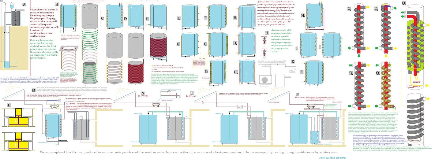


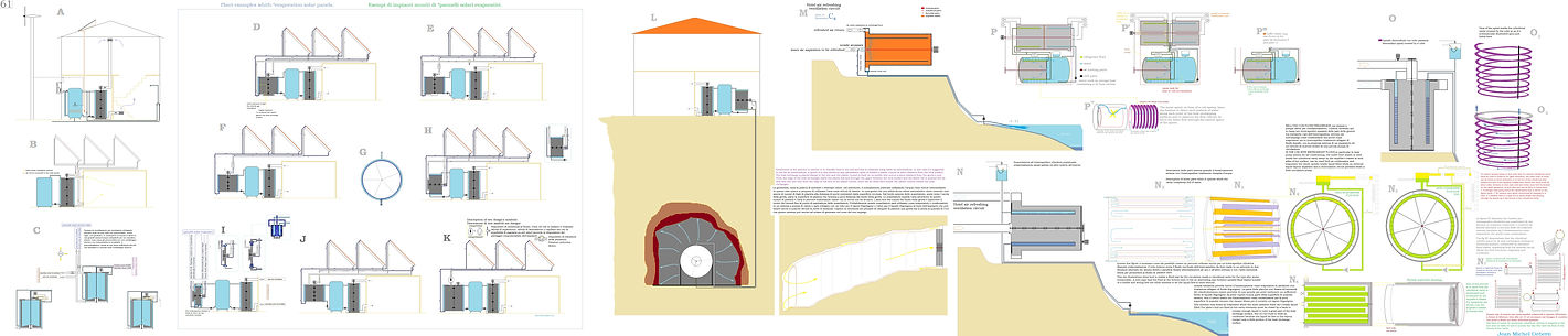


Table 68 : While Figures A are warnings for the construction of cylindrical cavities, Figures C and E show that at the ends of cylindrical heat exchangers, heat exchange elements can be added consisting of circular gaps with surfaces that are not only flat but also curved to better withstand internal and external pressure. Figures B and C are water- refrigerant heat exchangers with the latter occupying the environment of the impeller, Figures D and E are air- refrigerant heat exchangers with the refrigerant occupying the interior of the cylindrical cavity, but whereas in Figure D the air flow exits from the scroll at the bottom, in Figure E the impeller is made so that the air enters and exits from the upper central part of the heat exchanger. Fig. F refers to the fact that when an impeller also sweeps the outer surface of a cylindrical cavity, a ring of baffles attached to the cavity or outer casing of the heat exchanger can push a rotating air flow in a linear direction. Figure G shows a refrigerant heat exchanger - air, water or smoke, made to work in a horizontal position, whose heat exchange elements are hollow disks with labyrinth-type inserts. This configuration is suitable when it is feared that the flow will bring with it substances that could settle on the heat exchange surfaces.
Table 69 : SHALLOW GEOTHERMAL IN THE FORM OF HEAT EXCHANGE WITH THE GROUND USING AIR AS THE HEAT TRANSFER FLUID. In heating mode, this function allows not only to extract heat from the ground, using an air flow as a heat transfer fluid, but also derives an additional source of heat from the condensation of moisture that the contact with the ground transmits to the air flow. Obviously, the underground air must not be fed into the living space, but must be passed through a heat pump or a very efficient air-to-air or air-to-water heat exchanger. This is a more efficient and environmentally friendly alternative to building plants by depositing and leaving kilometres of plastic pipe in the ground after excavation. The figures A show two modes of condensation, in figure A1 on the left, the usual procedure is shown, improved through a continuous circulation of steam through the heat exchanger performed with a fan. This increases the flow rate of the steam on the surfaces, improving the heat exchange. The second figure A2, on the other hand, shows the application of the new physical condensation process for which a patent has been applied for. In the mode drawn, there is no need for a liquid-vapour separator. Fig. A3 shows that instead of a rigid pipe passing through the coils of the inner spiral as seen in fig.A1, one or more flexible pipes can be passed between the coils to the bottom of the exchanger. Fig. B, without the need for major excavations, suggests that heat exchange with the ground can be achieved by constructing an air flow duct on the inside or outside of the wall of a building's perimeter cavity. Figure C suggests doing geothermal with groundwater from an aquifer vein, taking it upstream and feeding it back downstream of the vein after heat exchange. I would like to mention that water veins are commonly found at a depth of a few metres and were searched for when wells were dug and constructed by hand. Fig. D, D2 shows possible low solid brick walls to form a cavity in which a flow of air could flow from a release point to a withdrawal point, covering the area of a rectangular plot of land, for example, even several metres below a single-family house or in an adjacent free area even outside the perimeter of the building. Fig. E2 imagines filling an overburden with large stones in such a way that a flow of air can flow through the space between them, and in order to give this structure more stability and to channel the flow of air, one imagines placing layers of concrete between them. In this way, the thermal inertia of the rock mass used can also be exploited. It is advisable to use strong concrete pipes that are difficult to crush, in order to channel the outflow and return of air flows. Fig E A flow of air is pushed downwards and rises between the rocks, up to the crawl space, an empty space under the floor of the house. Fig D2, low walls of bricks and large stones with a concrete cover create a zig-zag path under a dwelling or contiguous ground. Figure F - L an excavation machine makes large holes in the ground. Vertical probes are placed in the holes, which are connected by horizontal ventilation sections or with a slope between one probe and the other in order to keep the ducts clean by allowing impurities and condensation water to fall to the bottom of the probes. Fig. L shows a mesh cylinder placed in the hole to prevent the penetration of soil and mud. After placing some stone at the bottom of the pit, a vertical plastic pipe is inserted and more stone is placed in the space between the netting and the pipe. Subsequently, a concrete box divided into two halves is placed on top to allow for the insertion of ventilation pipes before being covered with soil. The airflow descends through the stone and rises through the central pipe. Then a concrete box divided into two halves is placed on top so that the ventilation pipes can be inserted before being covered by the soil. The air flow descends through the stone and up the central pipe.
Table 70 a : The first images at the top left and the two figures A and B are just disquisitons about cylinrical cavities of dr heat exchanger. It is explained that, for heat exchangers where the external side of its cylindrical cavity is also swept by the impeller, the inlet and outlet of the fluids may only be possible from the same end of the cavity, and in that case, it can be an excellent solution for the internal spiral to be made up of a single tube or multiple concentric tubes. It is also possible to insert two or more identical spirals of tube within the same cavity. For example, in the case of the new condensation process, one coil discharges the refrigerant vapor to be condensed along with the recirculation liquid, while the liquid for recirculation enters through the other. The use of multiple spirals in the same cylindrical cavity, however, generates more than one path for the fluid within the cavity and I don't see an advantage from this. fig. C this time there is a concentric series of cylindrical cavities interspersed with wide spirals for the passage of air flows driven by a centrifugal fan. This scheme can be realised not only in a circular form, but also in a rectangular one. A scheme similar to a cylindrical interspace heat exchanger with a heat exchange element consisting of a cylindrical interspace with a spiral insert. It could be made for an industrial mixer heated or cooled by a heat pump or by a hydronic heat exchanger. Fig C' , Flat panels or rectangular structures, even open on one side, that are cooling or heating, can also be made with labyrinth-shaped inserts. Figs I, J, K, L are heat pump system layouts with cold or hot water storage tanks equipped with internal refrigerant-water heat exchangers consisting of a spiral formed by two concentric tubes squeezed between two cylindrical surfaces, so that water flows both around and inside the spiral. They are used to power hydronic heating or cooling systems with radiant surfaces or fan coils. In figure I, the circulation of the refrigerant liquid through the pump serves to create a current that transports the refrigerant vapor formed towards the separator. In fig. J, there is an optional circuit with a fan that circulates the refrigerant vapor to promote the condensation of the vapor. Figures K and L depict the same installation functioning as a condenser for hot water production and as an evaporator for cold water production. Fig. M shows the circuitry for the application of the new condensation process for hot water production.
Table 70 b : It is possible to connect an additional condenser for the production of domestic hot water to a heat pump system for heating and cooling, which can operate in conjunction with the system's condenser, be excluded from it, or temporarily take its place when the main condenser (e.g. for domestic heating) is not in use at the time. When, on the other hand, in the warm seasons, the water contained in the tank is already hot, the condenser function can return to the main exchanger which, for example, dissipates heat to the outside. The scheme is in essential form for understanding and obviously some valve needs to be added.
Table 70 c : In this example, the tank has two spiral heat exchangers both located between the same two cylindrical surfaces. The first one, which has a large diameter, facilitates heat exchange between the internal water of the tank and an air flow coming from a thermal solar panel installation, while the second one, with a small diameter, enables thermal exchange between the water in the tank and the refrigerant fluids of a heat pump system and as such, it could perhaps even be connected to an air conditioner of sufficient size, as shown in the figure. There is then a third heat exchanger with concentric circular profiles that serves to transfer heat from the tank to the home's air. While the device in the figure is designed to use the ordinary condensation process, the one illustrated in the window to the side is designed to utilize the new condensation method. In this latter case, a third tube is provided for the return of the non-condensed refrigerant vapor. This can happen when the thermal power of the system is increased and, with a larger volume of steam to be condensed, part of it may pass through the condenser without being condensed. To remove this uncondensed vapour, I thought of a float in the liquid-vapor separator with an electric control that opens a valve allowing access to the compressor suction or to the evaporator inlet.
Table 71 : Attention, this dr heat exchanger may still look identical to many others already shown but it is different. The heat exchange element is somewhat related to cylindrical cavities and the surface with concentric circular grooves but it is the insert that makes it radically different. This insert is indeed an impeller made up of one or more rotating concentric cylinders that extend like a barrier within these cylindrical grooves of the heat exchange surface stopping a short distance from the inner end of the cylindrical cavities. It can be designed to operate in a vertical or horizontal position. The inside of this cavity is divided into two environments by this barrier, so that the fluid injected at the end of one of the two environments must cross the edge of the inner cylinder to reach the other side of the same end. Since the outer surface opposite to these heat exchange elements is also exposed to the fluid moved by the other impeller, this heat exchanger should prove to be very effective. It is recommended that, in the function of the condenser, the horizontal working position and the new condensation process be adopted as illustrated in figures B, C, D, E. What produces a pressure differential for the circulation of a fluid through the exchanger can be a pump if it is a liquid fluid, but generally, it is the rotation of the impeller that should produce sufficient pressure differential in moving the fluid from the center to its edge, and to enhance this effect, at the edge, the impeller may have a crown of deflectors.
Table 72 : BACK TO THE SUBJECT OF AIR FLOW GEOTHERMAL ENERGY.
Fig. A shows how to take advantage of a soil configuration, how it can be a hill, to facilitate the construction of a thermal battery based on a large mass of earth and rock by facilitating the necessary excavation and construction of air ducts capable of exchanging heat and collecting moisture to condense for further heat by means of underground air ducts made of porous natural materials. The idea behind Fig. B is that the ventilation air is first heated or cooled by a first heat exchange with a part of underground air flow, and then, to reach the desired temperature by a subsequent second heat Exchange, via a heat pump with the other part of the ground air flow. The heat pump integrated in this heat exchanger in turn exchanges heat with the underground air flow, but possibly not after the first heat exchange has already altered the temperature of the ground air, but if the flow rate allows it, simultaneously so as to act with maximum efficiency. Figures C and D show how spiral air paths can replace an impeller in various stages of implementation of this device. Figure F shows a possible plant layout of this airflow geothermal heat pump system, in which evaporator and condenser are located in two different units.
Table 73 :ALTERNATIVE SCHEMA OF ABSORPTION CONDITIONING WITH WATER AND AMMONIA SOLUTION SUPPORTED BY THERMAL SOLAR AIR FLOW AND INDIFFERENT TO HOT CLIMATIC CONDITIONS.
In this description, there is no compressor in the refrigeration fluid circuit, therefore it represents an absorption system. The special compressor represented acts on the air of the solar thermal circuit, which constitutes the heat source of the generator.
Table 74 : The evaporation of water in dry summer air, absorbs heat, producing coolness but it also makes the air more humid. In this proposal, the air made humid is expelled after cooling the water in the interspace, beyond the cylindrical heat exchange surface. The air flow that is pushed into the spiral inside the cylindrical cavity is cooled without becoming more humid. It should be noted that the water must not evaporate beyond the amount that turns into a saturated solution, otherwise there will be intense limestone deposits on the heat exchange surface. To avoid this, it is necessary to identify a minimum flow rate that depends on the degree of evaporation, which in turn depends on the air temperature and relative humidity. This means that part of the water must reach the bottom of the exchanger and be disposed of by either reusing it for watering or returning it to the well. In the second figure, the former device also incorporates a storage tank, covered with thermal insulation, to acquire greater thermal storage capacity while the spiral is designed to condense or evaporate refrigerant. The condensation mode considered ideal is the new condensation process because the ordinary mode would be too slow. When the outside air temperature is no longer deemed favourable, the impeller is stopped and the heat exchange of the refrigerant fluid continues in the cavity by means of the pump on the recirculation circuit, with the hot or cold water contained in the tank.
Table 75 : Apart from economic considerations, using air instead of water as a heat transfer fluid for solar thermal panels offers a unique possibility. Water is incompressible but air is not, and when air is compressed, its temperature increases. The compression of a mass of air that, due to the season or the late afternoon hour, a solar thermal panel installation fails to provide more than 60°C = 333°K, would raise its temperature to 406°K = 133°C, sufficient to operate an absorption heat pump, continue a heat exchange, or make industrial applications. Compressing air, however, has a high energetic and economic cost mitigated by the fact that we start from air already heated by the solar thermal system, and proceeding as illustrated in fig. A with a normal compressor and a pressure reducing valve would not compensate for the heat gain because the energy spent for the compression of the air is, from a purely kinetic point of view, completely lost after the pressure reducing valve or expansion valve, referred to generically in this work as valve R, with R intended as resistance to flow. The compressed air that passes through a heat exchanger exits cooler, and the decrease in pressure due to its contraction from cooling is not significant. Therefore, when lowering the pressure of the outgoing air, it is advisable to recover its kinetic energy due to the pressure rather than just wasting it. In hydroelectric reservoirs it is sometimes possible to pump the water back into the dam to reuse its potential energy at a later time. In this case, the dam is equipped with turbines to generate energy from falling water and pumps to lift it into the reservoir. The shape of these pump and turbine impellers can be quite similar. If, absurdly, one were to suppose to pump water up with a pump and let it fall into a turbine, then if purely conjecturally, one were to disregard all losses, the effect would be null because the energy needed for one would be supplied by the other. However, in reality, the turbine could only compensate for a part of the energy required by the pump, but what interests us is that the water from the dam, upon exiting the turbine, retains a residue of its potential energy. This means that if we imagine the dam as a heat exchanger and the pump as the centrifugal compressor, the turbine acts like a pressure reducing valve or expansion valve, with the difference that it has recovered some of the energy. In doing this, it is advisable to place the compressor impeller on the same axis of rotation as the impeller that acts as a turbine, so that it can work together with the electric motor to rotate the common axis of rotation by means of the recovered kinetic energy. The residual unrecaptured kinetic energy can be used to circulate the airflow through the circuit of the solar thermal panels. The compressor illustrated in Figures B and C is based on this principle. The two coaxial impellers have different diameters because, as mentioned, the outgoing air must retain a residual energy necessary for its circulation through the assembly of solar panels. Two impellers coupled into one sharing the same scroll, as shown in Figure D 7, is not suitable; each impeller must be in its own scroll, as shown in Figure D 8, otherwise there would be parasitic air flows from the larger to the smaller one. Furthermore, the two coupled scrolls also have different widths, so that the airflow exiting from the exchanger is faster when passing through the turbine and strikes the turbine blades more effectively. Regarding the cylindrical cavities of the heat exchangers, the impeller sweeps over the external side of the cylindrical space, and the fluid pumped at the bottom of the space must be able to return without the need for a duct external to the surface of the space. In the case proposed in figures E and F, the interior space of the cylindrical cavity is divided into two areas by a cylindrical surface that comes close to the bottom of the space. By crossing the edge of this surface, the fluid can return by ascending the other side of this cylinder. The inserts of this cavity are therefore two spirals positioned on each side of this cylindrical surface.
Table 76 : These air-air or air-water heat exchangers differ and are therefore alternative to those explained in the first part of the site and for which a patent was applied, they are not actually made up of a spiral with three or four concentric tubes, but from a spiral made up of a single-tube or two concentric-tube clamped between two cylindrical surfaces. Here, between figures A and G, it is proposed to realise a monobloc heat pump system consisting of two cylindrical exchangers lowered one inside the other but separated by thermal insulation such that one constitutes the condenser and the other, the evaporator of the system. In Figures H and I, however, it is proposed that the internal exchanger of the packaged system for air conditioning be a cylindrical cavity.
Table 77 : Figures A to H are hypothesis-based reasoning for understanding the operation of this energy recovery centrifugal compressor. It is worth returning only to figure G to understand that no matter what speed we wanted to give the centrifugal compressor, as designed, it would be irrelevant and that, despite the air being pressurized in the heat exchanger, the circulation in the rest of the circuit occurs only due to the effect of the applied centrifugal fan E. Instead, in the adjacent figure H, there is no need for the fan E because it is due to the difference between the diameters of the scrolls and the impellers that the device can generate head and thus circulation in the rest of the circuit, and since this solution also sends pressurized air through the heat exchanger, this is the correct form of this device but as mentioned in the previous table, it may be necessary to reduce the thickness of the part that recovers energy by lowering the pressure of the outgoing air. Another thing to consider is that it is the peripheral speed of the impeller that determines the pressure generated; therefore, in a compressor with a smaller diameter, at the same peripheral speed at the edge of the impeller, there will also be less friction because there is less internal surface inside a smaller scroll. Figure X5 shows us a theoretical and a practical diagram of an air dryer made with this compressor. The simultaneous compression and cooling of the air causes the condensation of the moisture contained in the air, similar to a heat pump dehumidifier (which, unlike this, does so without compressing the air but condensing it on cooler surfaces), but with a simpler machine. The uses are various, such as dehydrating food to make dried fruit, accelerating the drying of wood, drying waste to facilitate its incineration, in the paper industry and other applications. While the figures N remind us of tanks with exchangers made up of a spiral tightly placed between two cylindrical surfaces, indicating that it can be found both inside and outside the tank, the figures O explain that the spirals tightly placed between the cylindrical surfaces can be two or more, twisted into one another. The U figures instead explain that, for this type of heat exchanger, which is very efficient in heat exchange between water and air, it is not mandatory to be wrapped around or located inside a tank, a tank that, it is worth remembering, is suitable to function as a thermal accumulator. The other figures show examples of air flow solar systems, figure P shows one not equipped with the energy recovery compressor, while figures P, W1, W3 show various system configurations including this compressor.
I do not recommend the solution to fig. Z because a hazardous fluid, such as refrigerant fluid, which is usually under pressure, is safer enclosed in a tube rather than in a gap between two cylindrical surfaces.
I thought I had found a new solution even in the field of elastocaloric heat pumps, but I realized that it still doesn’t work. However, upon request, I could return to work on it.
If you like this work, let's try not to let it sit in a drawer for twenty-thirty years, and if you're thinking about a study on prototypes, I am available to work on it for you. Unfortunately, to be honest, I am not graduated nor do I speak English perfectly.
You will find the tables reproduced in higher resolution at the following address:
https://drive.google.com/drive/folders/1wHPh3QqZ-666fSXH0x8vCSA-L472bYMU?usp=drive_link
WHAT IMPROVEMENTS CAN THE WORK DESCRIBED HERE BRING TO HEAT PUMP SYSTEMS
With a more efficient condensation and/or evaporation process, two things can be done. Either the thermal power is increased while maintaining the same efficiency, or the advantage is taken to lower the condensation pressure (raising its temperature) and/or raise the evaporation pressure (lowering its temperature) in order to reduce the pressure difference between the condenser and evaporator, which reduces the strain and consumption of the compressor, thereby increasing the efficiency of the system.
It must be said that the new condensation and evaporation processes described here are not very suitable for occurring in today's finned tube heat exchangers (finned pack heat exhangers), which are today almost the only ones used in thermal exchanges with air, and perhaps that is why other inventors have not perceived them. Moreover, every type of physical process is more suitable for certain environments of heat exchangers than for others, but the many illustrations contained here describe all cases.
The heat exchangers with concentric circular grooves present in tables 17b, 50, 51, 66, 67a, 67b, 71, 72, 73 are suitable for both the new evaporation process and an improved form of the traditional condensation process, but in the case of the cylindrical cavity heat exchangers, the environment of the impeller is suitable for the new evaporation process but not for the new condensation process described in the first part of the site, which can however take place in the cylindrical cavity of another heat exchanger of the same type.
In a detailed technical article published online by an engineer from an Italian air conditioning company, I discover that there are serious technical gaps concerning the current heat pump systems for air conditioning that are not often discussed. It reports that the efficiency of a machine or of an ordinary air conditioning system operating below its maximum thermal power, decreases significantly.
In current technical language, this phenomenon is called 'coefficient of performance at part load, COP (PL)', and it can drop to dramatically ridiculous values compared to the 'coefficient of performance at declared capacity', COP (DC). To the less experienced, I explain that, with the arrival of days with mild temperatures, when it is expected that the heat pump's consumption will decrease, this does not happen, as expected, due to a drop in efficiency levels.
On the contrary, in devices and systems that use different condensation or evaporation processes and the new types of heat exchangers, under the same circumstances, I expect rather an increase and not a decrease in efficiency. In my modest but alternative opinion, the causes of this phenomenon could be three or four.
As the primary cause, regarding the reduction in power of the compressor in a traditional heat pump system, I envisioned cyclical phenomena with pressure fluctuations but especially with oscillations in the level of liquid refrigerant present in the evaporator and condenser. In fact, an undesirable decrease in the level of liquid refrigerant in the evaporator and an increase in the condenser leads to temporary losses of utilization of a part of their internal heat exchange surface, resulting in a loss of efficiency of the system.
The second cause could be related to the priorities set in the current electronic control systems for maintaining the pressure differential between the evaporator and condenser, which cannot prevent the phenomenon from occurring. The third cause may depend on the nature of the heat exchangers used. If the percentage decrease in thermal power exchanged by them, is greater than the decrease in electrical power, supplied to the system for its operation, then the system's efficiency drops accordingly.
A fourth cause has instead been resolved for some time; it concerns the transition from intermittent operation of on-off systems to the modulated operation of inverter systems, but this alone has not provided a solution. However, let us return to a possible solution for the first cause mentioned above, provided that it takes place in the ways I have described. The new condensation process, I outlined in the first part of the site, stipulates that the internal environment of the condenser (or tank) is filled with liquid, just as happens in the classic, modern evaporation process.
Since liquids are nearly incompressible, in a heat pump system using for example the usual evaporation modality ad the new condensation process, working with both, the evaporator and the condenser, full of liquid, part of the liquid would not be able to leave the evaporator to flood the condenser, and the phenomenon of only partial utilization of the heat exchange surfaces of the condenser and evaporator could not occur. It is therefore likely that the development of new heat pump systems according to the methods here described, could solve the problems associated with traditional systems, gaining and maintaining high levels of efficiency in almost every situation.
However, an unprecedented evaporation process has also been presented here, and among the classic and new modes of evaporation and condensation, the combinations become at least four and will need to be analyzed and experimented on a case-by-case basis. But the loss of efficiency of current heat pump systems when operating at partial load is not their only problem; there is another issue that is even more serious.
In Europe, heat pumps have been called upon to replace boilers in the role of winter heating, and the problem I am mentioning arises when the evaporator, in order to absorb heat from the air, must go below the freezing temperature of water. The condensation of atmospheric moisture into water is unavoidable, but under such conditions, the heat exchanger freezes this water, becoming covered in ice, and if the heat exchanger consists of fins, as is the case with finned pack heat exchangers, the ice gets lodged between them, creating thick layers that insulate the evaporator from the air.
I read that, even at usual humidity values, the defrost cycles become so numerous that a heat pump becomes less efficient compared to a boiler, but above all the device can no longer provide sufficient thermal power. The heat exchangers described on this site have a heat exchange surface that is free of fins and grips; the formation of the same thickness of ice takes longer because the condensation droplets, detach from the surface before freezing.
In this way, the defrost cycles are not only fewer but also shorter because the ice can detach more easily from the surfaces without needing to be completely melted. If heat exchangers are adopted as evaporators, made with heat exchange elements consisting solely of disc-like surfaces coated externally with a non-stick treatment (such as Teflon), the ice, not being able to grip much on the surface, could be detached from the rotating blades of the impeller without the need for any defrost cycle, significantly preserving the best efficiency values.
If all these considerations are not enough, it can also be demonstrated with theory that the abandonment of finned heat exchangers improves the efficiency of the system. However, as an inventor, I am entering a very technical minefield, overseen by engineers, but I will dare to present my reasons in a necessarily general manner. A heat exchanger equipped with fins requires not only the necessary temperature difference to induce a heat flow between the internal fluid and the external surface but also an additional temperature difference for the heat transfer along the fins in order to interact with the airflow passing through them.
By avoiding this additional temperature difference, the evaporation temperature Te can be increased and the condensation temperature Tc can be decreased, and the formula, theoretical max COP = Te / (Tc - Te), where Te and Tc are indicated in degrees Kelvin, will provide higher values of COP efficiency. Therefore, why do engineers persist in choosing to design heat pumps with finned coil exchangers?
conditioning, according to traditional schemes? And why does no large manufacturing company fear that a competitor will start a change before others by launching new products on the market? If, on the other hand, some company wanted to at least conduct studies on prototypes, I do not have the expertise to replace an engineer but as the author, I have it as a technical consultant, to collaborate with them and certify that the prototypes are indeed what I have intuit.
A branch of cold fusion theory suggests that nickel atoms can be transformed into copper atoms by adding a proton to the nucleus of nickel, and since ionizing most isotopes of hydrogen produces precisely a proton, a simple process of water electrolysis in a nickel tank would be enough to carry out this reaction. I remembered an old article written by an engineer who claimed to have found traces of copper on the tank used in the experiment, and certainly this, if it were true, would support something.
However, some of these experiments used heavy water, and I thought that by dissociating it in an electrolytic process, it could become radioactive and produce heat. Furthermore, the atomic nucleus of nickel would repel the charge of a proton, and to force it in would be unlikely, so it is improbable that a high voltage alone would be sufficient, and it would probably be necessary to hit it squarely in the center by significantly accelerating it with a particle accelerator.
I therefore thought that, instead of an electrolytic bath, one could use the discharge in a vacuum tube as occurs in neon tubes because it produces ultraviolet electromagnetic radiation, and strong electromagnetic radiation can break down a nickel neutron into a proton with the emission of an electron, thus potentially reaching the number of protons of a copper atom, and this is the hypothetical experiment that I illustrated in the drawing.
An internet search tells me, however, that it should be very high-energy gamma-ray electromagnetic radiation, while ultraviolet radiation would not have enough energy. If the mental exercise I proposed to you in this last drawing could have been realized, a minimal investment of energy would have given us a lot of heat in return, but its probable impossibility tells us that, probably, in our near future, we have no alternative to heat pumps.
.
Jean Michel A. J. Deberti
jmdeberti @yahoo.com